
Every part we cast goes through the same set of design-for-manufacture checks — the same rules our instant quoting tool runs when you upload a model. This guide is the full reference: what the limits are, why they exist, and what to target so your part casts right the first time. All dimensions are pre-shrink CAD dimensions.
Process Overview
We cast using a lost-SLA ceramic shell process: an SLA resin pattern is invested in a ceramic shell, the pattern is burned out, metal is poured, and the shell is devested and finished.
- Process flow: SLA resin pattern → ceramic shell investment → burnout → metal pour → devest & finish
- Digital Metal materials: A356 Aluminum Alloy and 316L Stainless Steel
- Overall tolerance: ±0.1–0.3 mm on critical features
- Shrink allowance: +1.5–2.5% linear — scale your CAD before the pattern is printed (alloy-dependent; validate first)
Model Characteristics
Bounding Envelope and Aspect Ratio
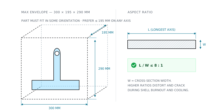
The bounding box envelope cannot exceed 300 × 195 × 290 mm. If the part cannot fit inside that box in any orientation, it is not castable. Prefer keeping every axis ≤ 195 mm; treat 200–250 mm as a caution zone.
- Aspect ratio rule: L / W ≤ 8:1, where L is the longest axis and W is the cross-section width. Higher ratios drive distortion and cracking.
Section Transitions and Mass Distribution
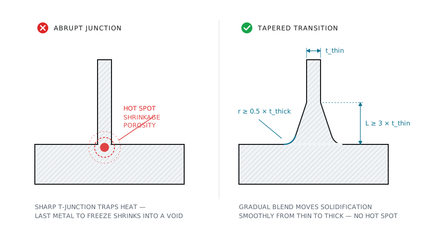
Abrupt section transitions cause shrinkage porosity as the material cools. Taper the cross-sectional volume between two large masses gradually, and never join thick to thin with an abrupt T-junction — that's where hot tears start.
- Taper / blend rule: blend length ≥ 3 × the thin wall thickness, with fillet radius ≥ 0.5 × the thick wall thickness. Gradual transitions prevent hot spots at thick-to-thin junctions.
Wall Thickness
Unsupported Walls
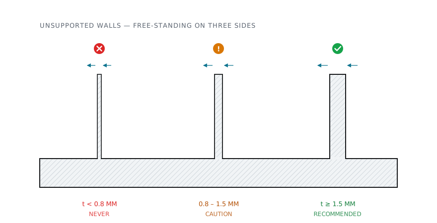
Free-standing walls unsupported on three sides:
- Never below 0.8 mm
- Caution at 0.8–1.5 mm
- Recommended design target ≥ 1.5 mm
Supported Walls and Floors
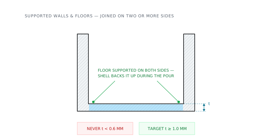
Floors and walls supported on two or more sides:
- Never below 0.6 mm
- Recommended design target ≥ 1.0 mm
Holes and Slots
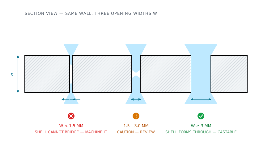
For every rule in this section, W is the narrowest opening width. It applies to circular holes, slots, and irregular cutouts alike — for a slot, W is the slot width, not its length.
Through Holes and Through Slots
- Never W below 1.5 mm
- Caution at 1.5–3.0 mm
- Recommended W ≥ 3 mm as-cast; narrower features should be machined after casting
- Castability rule: W / t ≥ 1/5, where t is the wall thickness the feature passes through, with W ≥ 3 mm as the absolute minimum
The controlling dimension is always the narrowest opening the ceramic slurry has to flow through, regardless of the feature's shape.
Blind Holes, Slots, and Pockets
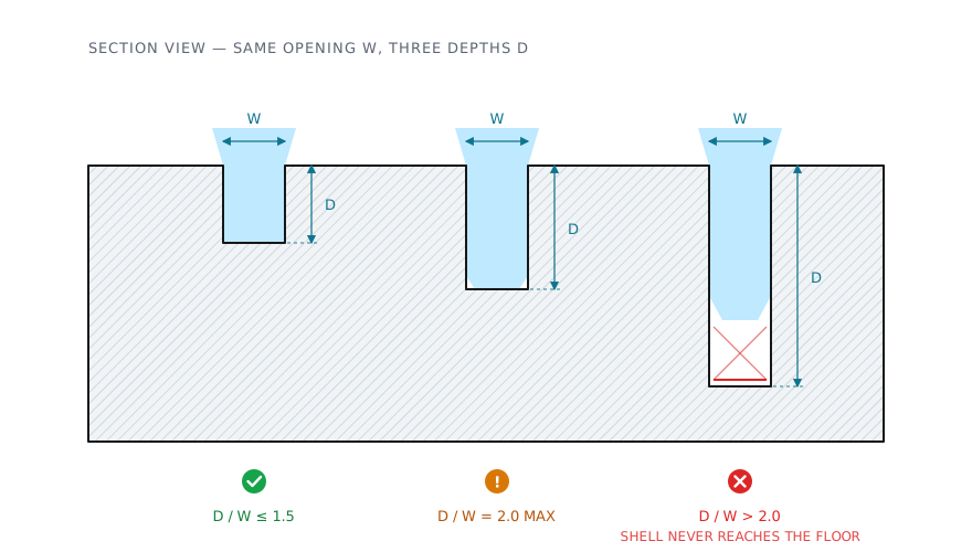
- Never deeper than D/W = 2.0
- Recommended D/W ≤ 1.5, where D is the depth from the open face to the blind floor and W is the narrowest opening
Gating
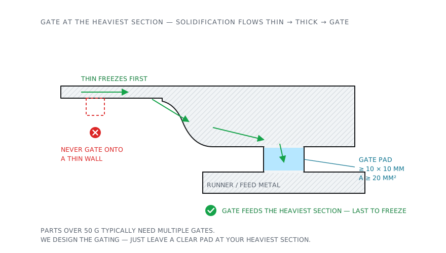
Gates feed metal into the mold and control how the part solidifies. Solidification should flow from thin sections toward thick sections, ending at the gate or riser.
- Gate at the heaviest section — never onto thin walls
- Gate sizing rule: gate area ≥ 20 mm², with a pad of at least 10 × 10 mm at the heaviest section
- Multi-gate parts heavier than 50 g
Internal Channels
Enclosed Volumes Need Drain Holes
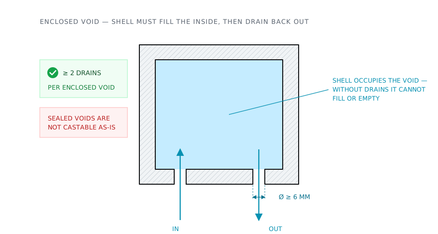
Fully enclosed voids are not castable as-is: the ceramic slurry needs a way in, and the shell material needs a gravity exit.
- Drain hole rule: diameter ≥ 6 mm, minimum 2 drain holes per enclosed void
Channel Diameter and Length
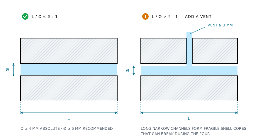
Narrow, long channels form fragile ceramic cores that collapse during the pour.
- Never below 4 mm diameter
- Recommended diameter ≥ 6 mm
- Length rule: L/D ≤ 5:1 without a vent; if L/D exceeds 5, add a vent of at least 3 mm
Internal Radii
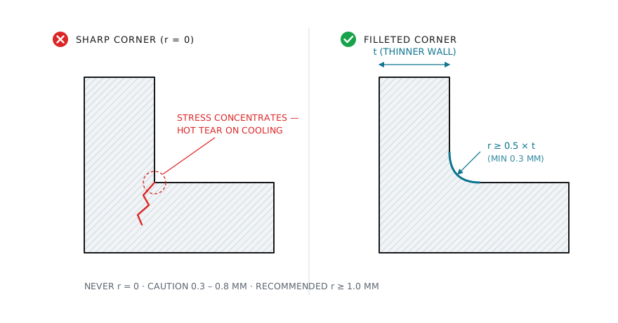
Sharp internal corners concentrate stress as the casting cools and are the classic starting point for hot tears.
- Never leave a corner sharp (r = 0)
- Caution at r = 0.3–0.8 mm
- Recommended r ≥ 1.0 mm
- Corner radius rule: r ≥ 0.5 × t, where t is the thinner of the two walls meeting at the corner, with 0.3 mm as the absolute minimum
Overhangs and Undercuts
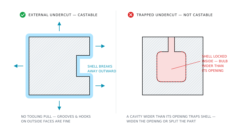
Unlike machining, casting handles external undercuts well — the shell forms around them. The failure mode is trapped undercuts: geometry that locks ceramic inside the part where it can never be removed.
- External, accessible undercuts: castable
- Trapped undercuts: not castable — the ceramic cannot be removed after the pour
Quick-Reference Summary
- Unsupported wall: min 0.8 mm, recommended ≥ 1.5 mm — free-standing on 3 sides
- Supported wall / floor: min 0.6 mm, recommended ≥ 1.0 mm — supported on ≥ 2 sides
- Section taper: blend length ≥ 3 × thin wall, fillet ≥ 0.5 × thick wall — prevents hot spots at junctions
- Through feature width: min 1.5 mm, recommended ≥ 3 mm as-cast — W/t ≥ 1/5; narrower → machine it
- Blind feature depth: D/W ≤ 2.0 max, recommended ≤ 1.5 — W is the narrowest opening
- Internal channel: min 4 mm Ø, recommended ≥ 6 mm — L/D ≤ 5:1 without a vent
- Drain holes: required on every enclosed void — ≥ 6 mm Ø, at least 2 per void
- Gate area: min 20 mm², pad ≥ 10 × 10 mm — at the heaviest section only
- Internal corner radius: min 0.3 mm, recommended r ≥ 0.5 × t — sharp corners cause hot tears
- Bounding envelope: 300 × 195 × 290 mm maximum — prefer ≤ 195 mm on any axis
- Aspect ratio: L/W ≤ 8:1 — higher drives distortion and cracking
- Shrink allowance: +1.5% minimum, typically +2.0–2.5% — alloy-dependent; validate first
Want these checks run on your part automatically? Upload a STEP file and our quoting tool flags every violation with the exact rule it broke — or read the interactive version in our DFM resource center.